TDI’s are notorious for having very poor heat output, especially in colder climates. VW finally did something about this and MKV TDI Jettas have an auxiliary 1000W electric heater installed just after the normal heater core inside the heating system. Gas powered vehicles like the GTI don’t have this heater because they heat up quicker, but as I discovered the place for the heater is still there.
This should with for both Climatronic and Climatic heating systems.
This will only work for Valeo heating systems and may only work on specific years.
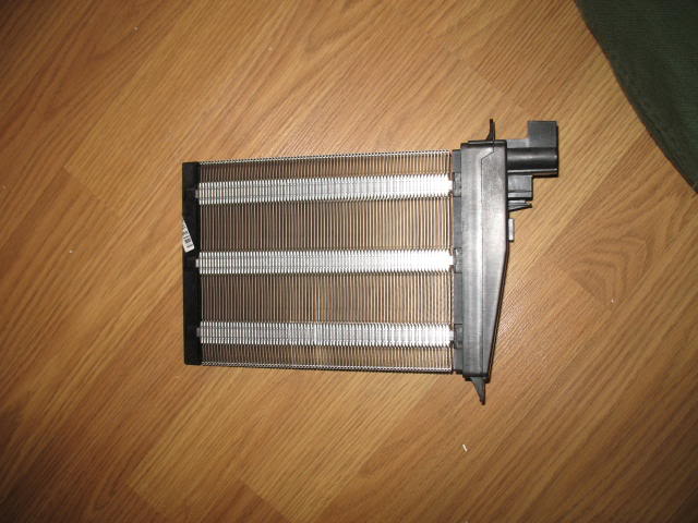
The heater:
Stage 1, Inside:
Tools:
T25
6mm socket
Parts:
PTC Heater 1K0 963 235 E (from German eBay)
Cover 1K1 819 349 E (optional)
10 feet 4AWG wire
4x 4 AWG ring connectors
Electrical Tape/zip ties
Connector 1K0 972 704 C
Repair wire 000 979 009
2 6mm nuts from the hardware store
Step 1, Gain access to the heater.
The heater is installed on the right hand side inside the driver’s footwell.
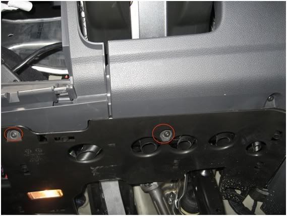
Remove these 2 screws (red), they are both T25:
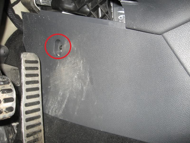
Remove this screw, it is T25 as well:
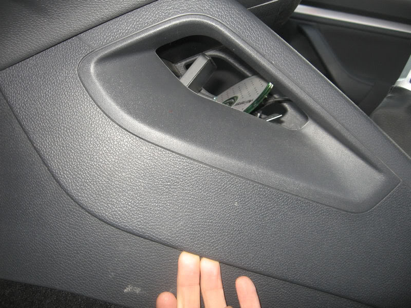
To remove the panel you will need to pull back slightly on the overlapping portion shown here:
Step 2, Remove the stock cover.
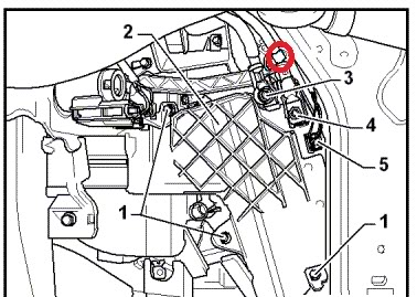
Here we see a drawing of the heater installed. Remove the 3 screws marked number 1. There is one more bolt not in the picture is located in red:
With the cover removed you can install the heater into the slot behind it, use 2 of the cover bolts to attach the heater.
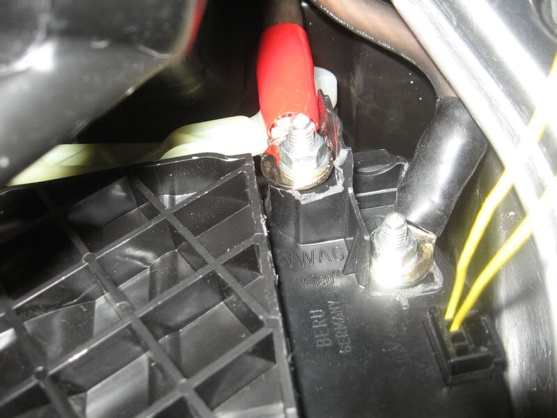
Here is an image of the installed heater. You may need to trim some plastic around the terminals depending on the size of your ring connectors:
In the above picture the cover has been reattached. The red line is where I trimmed off the plastic where the cover is now. The 3 remaining bolts were used to attach the cover. Here is the piece I trimmed off:
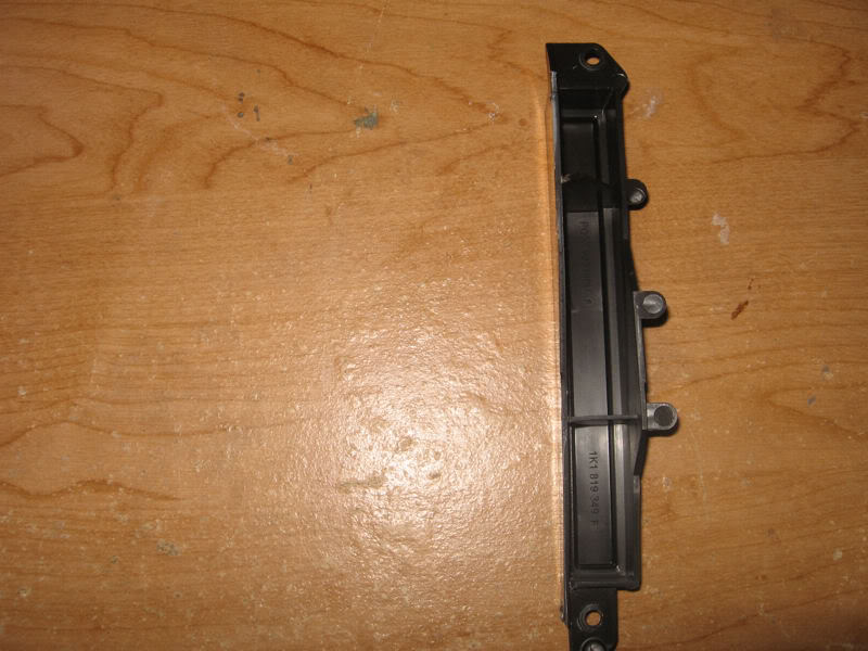
The bolt holes at the top and bottom are in the same position as the 2 holes used to attach the heater itself.
Step 3, Positive and ground connections.
The heater uses around 80 Amps of current, this is a lot of current and if the connections are not made good enough we could cause a fire. There was actually a TSB for the nuts on the heater not being tightened enough from the factory causing a fire I believe.
Cut the 10 feet of wire into 2 pieces, 1 4 feet and the other 6 feet.
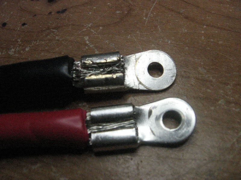
Attach 1 connector to the end of the wires, 4 in total. I crimped the connections, soldered them to the wire and added sleeves to the connectors
Here is an example:
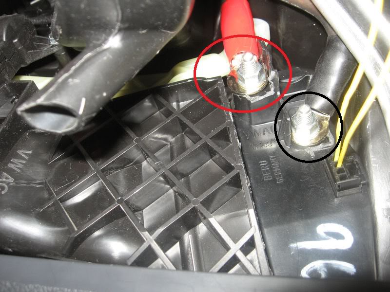
Attach the wires to the heater using the 6mm bolts. Make sure you have the negative wire on the (–) terminal and the positive wire to the (+) terminal:
Step 4, Wire the data connection:
The heater has a direct connection to the comfort CAN bus. The nearest location of the bus would be the Data bus diagnostic interface.
The pins are not visible so we are looking for the orange/brown and orange/green that are twisted together. Cut the repair wire in half and attach 1 end to each of the wires and to each of the bus wires.
The module is the black box with the red plug in it, the object in the blue box is the top of the brake pedal. Circled in red is there the wiring connections are made:
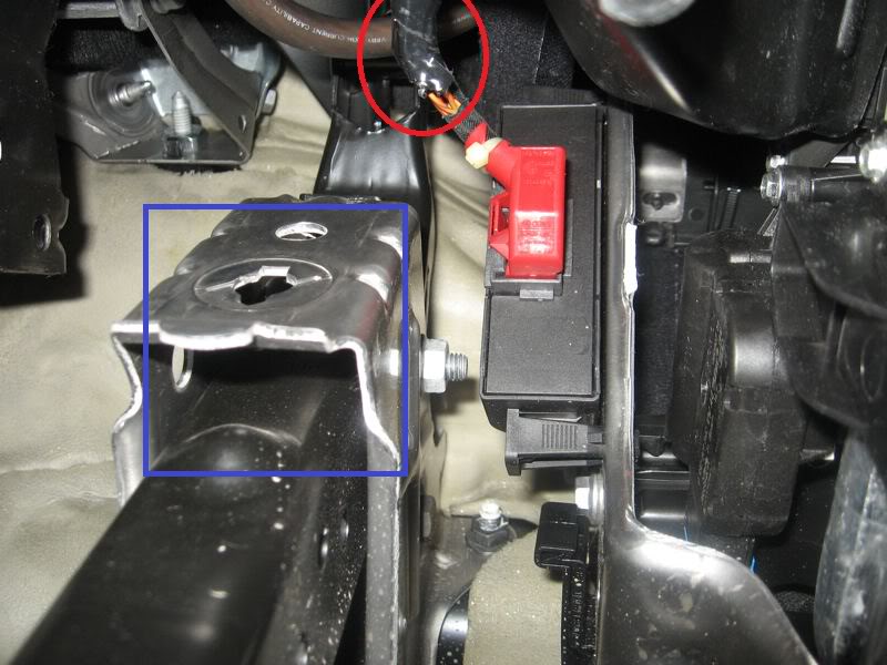
The repair wire attached to the orange/green wire goes into pin 1 and orange/brown goes into pin 2.
Plug the wire into the heater (red):

Step 5, Negative wire to the chassis.
Remove the left kick panel to access the ground post. Instructions can be found in the sub install DIY http://forums.vwvortex.com/zerothre...dit: Sept 25/2017, Updated photo links. -Cad
This should with for both Climatronic and Climatic heating systems.
This will only work for Valeo heating systems and may only work on specific years.
The heater:
Stage 1, Inside:
Tools:
T25
6mm socket
Parts:
PTC Heater 1K0 963 235 E (from German eBay)
Cover 1K1 819 349 E (optional)
10 feet 4AWG wire
4x 4 AWG ring connectors
Electrical Tape/zip ties
Connector 1K0 972 704 C
Repair wire 000 979 009
2 6mm nuts from the hardware store
Step 1, Gain access to the heater.
The heater is installed on the right hand side inside the driver’s footwell.
Remove these 2 screws (red), they are both T25:
Remove this screw, it is T25 as well:
To remove the panel you will need to pull back slightly on the overlapping portion shown here:
Step 2, Remove the stock cover.
Here we see a drawing of the heater installed. Remove the 3 screws marked number 1. There is one more bolt not in the picture is located in red:
With the cover removed you can install the heater into the slot behind it, use 2 of the cover bolts to attach the heater.
Here is an image of the installed heater. You may need to trim some plastic around the terminals depending on the size of your ring connectors:
In the above picture the cover has been reattached. The red line is where I trimmed off the plastic where the cover is now. The 3 remaining bolts were used to attach the cover. Here is the piece I trimmed off:
The bolt holes at the top and bottom are in the same position as the 2 holes used to attach the heater itself.
Step 3, Positive and ground connections.
The heater uses around 80 Amps of current, this is a lot of current and if the connections are not made good enough we could cause a fire. There was actually a TSB for the nuts on the heater not being tightened enough from the factory causing a fire I believe.
Cut the 10 feet of wire into 2 pieces, 1 4 feet and the other 6 feet.
Attach 1 connector to the end of the wires, 4 in total. I crimped the connections, soldered them to the wire and added sleeves to the connectors
Here is an example:
Attach the wires to the heater using the 6mm bolts. Make sure you have the negative wire on the (–) terminal and the positive wire to the (+) terminal:
Step 4, Wire the data connection:
The heater has a direct connection to the comfort CAN bus. The nearest location of the bus would be the Data bus diagnostic interface.
The pins are not visible so we are looking for the orange/brown and orange/green that are twisted together. Cut the repair wire in half and attach 1 end to each of the wires and to each of the bus wires.
The module is the black box with the red plug in it, the object in the blue box is the top of the brake pedal. Circled in red is there the wiring connections are made:
The repair wire attached to the orange/green wire goes into pin 1 and orange/brown goes into pin 2.
Plug the wire into the heater (red):
Step 5, Negative wire to the chassis.
Remove the left kick panel to access the ground post. Instructions can be found in the sub install DIY http://forums.vwvortex.com/zerothre...dit: Sept 25/2017, Updated photo links. -Cad
Last edited:
