GOLFMK8
GOLFMK7
GOLFMK6
GOLFMKV

Parts for highline rear camera retrofit

Kushdaiin

Go Kart Champion
Location
Connecticut
Car(s)
MK7 R, MK7 GSW SEL
If going from low line to high line camera you can use most of the existing wiring but you have to move things around. Pin 3 from the latch assembly goes directly to pin 6 (on the eight pin connector) on the camera now. CANBUS high and low need to be wired separately from the camera to the back of the MIB as in @mr-fix DIY video. Video can be reused from the low line camera. The ground wire on the camera side should NOT be connected to anything, as it was in the low line camera. +12V can be taken from the original camera connection.
 

DV52

Drag Racing Champion
Location
Australia
What @mr-fix said - but in picture form:


Kushdaiin

Go Kart Champion
Location
Connecticut
Car(s)
MK7 R, MK7 GSW SEL
@DV52 I've done this retrofit twice on my R and my GSW. While these diagrams are helpful it's not the full picture for the MK7 Golf with the low line camera. 1. Power for the low-line camera is paralleled with the latch mechanism through to SC18. 2. Ground coming out of the low-line camera is not wired into an adjoining pin as shown on the diagrams above. I tied the ground to the post below the right side A-pillar. It wouldn't work and the module threw a short-to-ground Code. Once removed, everything worked. The only wires coming out the plug adjoining the camera are the BCM and power. I still have a picture of that on my phone, because it boggled my mind upon seeing it.
 

ricardosoa

New member
Location
Brazil
Car(s)
GOLF GTI MK 7.5
wiring needs to be changes.
LOW vs HIGH camera have more differences than just the CAN-BUS connection.
You need to disconnect reverse bulb signal from the camera/mechanism. This signal will be detected via CAN-BUS now. Camera will control the mechanism.
Whole wires? Or just can bus? Because can bus I changed
 

DV52

Drag Racing Champion
Location
Australia
@DV52 I've done this retrofit twice on my R and my GSW. While these diagrams are helpful it's not the full picture for the MK7 Golf with the low line camera. 1. Power for the low-line camera is paralleled with the latch mechanism through to SC18. 2. Ground coming out of the low-line camera is not wired into an adjoining pin as shown on the diagrams above. I tied the ground to the post below the right side A-pillar. It wouldn't work and the module threw a short-to-ground Code. Once removed, everything worked. The only wires coming out the plug adjoining the camera are the BCM and power. I still have a picture of that on my phone, because it boggled my mind upon seeing it.
OK - thanks for the comment! Not sure why you had this experience - not happened to me!

Anyhow -here's a copy of the official wiring diagram from VW for an OEM camera (with ALL the associated complexity that is avoided in my diagram )


I've highlighted the earth wire in question. As is clear and again this is how RVCs are wired on the VW production-line, there is an actual, physical brown-colored wire (cross-sectional area 0.5mm2) connected to pin #2 that terminates on THK (which is the coupling point on the rear hatch lid). Eventually this wire finds an earth point on the car chassis. This is the main earth wire for the RVC and it's replicated in kind on my diagram!!

Could it be (perhaps) that your 2 x installations used after market RVCs from a third-party manufacturer. If so, anything is possible on non-OEM equipment. Perhaps these non-OEM cameras might have relied on some form of case-earth - but if this is the case, it's very strange that also earthing pin #2 caused a problem (after all, these 2 x earth points are at the same electrical potential - if the OEM pin pattern is followed)

Don
 
Last edited:

Kushdaiin

Go Kart Champion
Location
Connecticut
Car(s)
MK7 R, MK7 GSW SEL
It was odd and no, neither of the low-line cameras were aftermarket or third party. On top of that, the R was manufactured in Germany and my GSW in Mexico. Either way, there is a 4-pin intermediate connector between the camera and the 10-pin THK connection shown above. This was consistent on both cars.

The image below is from the camera to the 4-pin connector. Here you can clearly see the power (pin 1), ground (pin 2), and BCM connection (pin 4). This arrangement is in alignment with the diagram above.
IMG-6154.jpg

This was the other side of the 4-pin connector before the highline retrofit. There was no ground wire through this connector back to the THK. This picture was take on my R but was consistent on the GSW as well. I bought the highline kit from carsystems.eu, which supplies a harness assuming you have no RVC, just the latch. Initially I routed all of the harness and connected a ground to the other side of the 8-pin connector for the highline camera, which caused it to not work. Once removed, and after repinning pin 3 from the latch to pin 6, everything worked as design (with coding). As noted above, wiring the ground caused a the module to throw a short code. That code disappeared after removing the ground wire.
wiring to camera.jpg
 

DV52

Drag Racing Champion
Location
Australia
@Kushdaiin :

OK - your first picture is OEM compliant because it shows the same set-up as in the official VW wiring diagram the I posted.

I assume that the missing earth wire on your 2nd picture ("the other side of the 4-pin connector") is simply because the main earth connection happens (somehow) through one of the bolts securing on the RVC housing.

My hunch is that this deviation from the OEM wiring arrangement is a post wiring diagram production variation - but again, I'm guessing. However, the fact of the the missing wire in your second picture changes nothing about the electrical set-up for the low-line camera. Pin #2 - is still at earth potential (because the wire in your first picture is eventually earthed at the point labeled "256" in the OEM wiring diagram) AND the low-line camera is still connected to the same electrical potential as pin #2 on the 4 x pin connector (albeit in your cars via a housing bolt)!

I make no comment about the wiring arrangement for the upgrade arrangement because both the hi-line camera AND the new wiring harness were sourced from a non-OEM supplier. Again without intending any offense - VW never envisaged an electrical set-up in their factory wiring looms where a carsystems.eu hi-line RVC harness was used to supply non-OEM equipment.

I really have no idea why you experienced your problems - but again with no offense intended (and IMO, of course) it's highly unlikely that the cause was because the OEM wiring diagram (which I still maintain is faithfully replicated in my picture) is somehow deficient.

Instead, I respectfully suggest that the cause of this problem is related to the fact that non-OEM equipment has been used. Maybe your understanding about how the non-OEM harness was designed was/is "incomplete" (no offense), or maybe the particular harness that was used was not apprpriate given your words that the "harness assumes you have no RVC" (which was not the case). I just don't know - but again, it's far more likely that somewhere in these questions about no-OEM equipment, the underlying cause for your obsevations can be found (IMO, or course)

Don
 
Last edited:

Kushdaiin

Go Kart Champion
Location
Connecticut
Car(s)
MK7 R, MK7 GSW SEL
@DV52

Don, I understand your position and take no offense to your observations. I can certainly understand your perspective, as I've never run into an inconsistency with the OEM wiring diagram (as an aside, the master mechanic at my local VW dealership laughed when I said I was using the OEM wiring diagrams because his position is that they're rife with inaccuracies, to which I don't necessarily agree). While I'm not super adept at electrical wiring (mechanical engineer), I think I've been able to deduce the configuration based upon the OEM diagrams. In fact, I was able to reduce the carsystems harness down to only three wires needed to make it align with the OEM wiring diagram and to get it working.

Anyway, my only point is that that ground coming from the OEM installed low-line camera which came from the factory, did not have a mating pin. The low-line camera may be grounded through different means, but the reality was in both cars that the pin 2 did not have a mating pin on the mating connector. Ergo, adding a ground through pin 2, as noted in the diagram above, caused a short error in the module. That was my simple observation using OEM equipment with a single wire connecting the mating pin 2 to a ground post below the a-pillar on the right side of the car. So, to make it work, I simply aligned the highline camera wiring to be nearly in line with the low line camera wiring and voila! It worked. We could discuss this ad nauseum but it won't change the fact that the camera worked with the only wiring deviation having the ground not wired.

I do appreciate these discussions though, because you are a wealth of knowledge and I sincerely appreciate what you've done to expand the knowledge base of the MQB platform for the enthusiast community. I've used your documented knowledge more than once!
 

Meesters

New member
Location
Belgium
Car(s)
Golf 7.5 Variant
Got a second-hand highline camera for my wagon. Tested it briefly just to confirm that it works. If anyone is interested in watching the test, here it is:

Well done and great video! Would you be so kind to share the part number for Golf 7 Variant? Since I'm thinking about upgrading my lowline version.

Great thanks!
 

mr-fix

Drag Racing Champion
Location
Poland
Car(s)
MK7 2.0TDI Variant

  • VW Golf MK7 hatchback:
    5G0-827-469-H; 5G0-827-469-P; 5G0-827-469-R; 5G0-827-469-T, 5G0-827-469-AF
  • VW Golf MK7 estate/variant:
    5G9-827-469-G; 5G9-827-469-H; 5G9-827-469-Q; 5G9-827-469-S; 5G9-827-469-AA, 5G9-827-469-AG, 5G9-827-469-AJ.
  • VW Golf sportvan:
    510-827-469-E, 510-827-469-G, 3G0-827-469-BL, 3G0-827-469-CA, 3G0-827-469-CJ, 3G0-827-469-FL, 3G0-827-469-FS.
  • VW Passat B8 estate/variant and Arteon coupé with back glass high polished logo:
    3G0-827-469-E, 3G0-827-469-H, 3G0-827-469-E, 3G0-827-469-L, 3G0-827-469-AA, 3G0-827-469-AQ, 3G0-827-469-BB, 3G0-827-469-BJ, 3G0-827-469-BL, 3G0-827-469-BS, 3G0-827-469-CA, 3G0-827-469-CG, 3G0-827-469-CJ, 3G0-827-469-FL, 3G0-827-469-FL, 3G0-827-469-FS, 3G0-827-469-GC, 3G0-827-469-HN.
  • VW Passat B8 estate/variant and Arteon coupé with black/bright chrome logo (new logo from 2020):
    3G0-827-469-EK, 3G0-827-469-ER, 3G0-827-469-FE, 3G0-827-469-HE.
  • VW Passat B8 sedan and Arteon sportback with back high glass polished logo:
    3G0-827-469-F, 3G0-827-469-CD, 3G0-827-469-FM, 3G0-827-469-FT, 3G0-827-469-HK.
  • VW Passat B8 sedan and Arteon sportback with black/bright chrome logo (new 2020 VW logo):
    3G0-827-469-EG, 3G0-827-469-EN, 3G0-827-469-FL, 3G0-827-469-FH, 3G0-827-469-HB.
 

Meesters

New member
Location
Belgium
Car(s)
Golf 7.5 Variant

  • VW Golf MK7 hatchback:
    5G0-827-469-H; 5G0-827-469-P; 5G0-827-469-R; 5G0-827-469-T, 5G0-827-469-AF
  • VW Golf MK7 estate/variant:
    5G9-827-469-G; 5G9-827-469-H; 5G9-827-469-Q; 5G9-827-469-S; 5G9-827-469-AA, 5G9-827-469-AG, 5G9-827-469-AJ.
  • VW Golf sportvan:
    510-827-469-E, 510-827-469-G, 3G0-827-469-BL, 3G0-827-469-CA, 3G0-827-469-CJ, 3G0-827-469-FL, 3G0-827-469-FS.
  • VW Passat B8 estate/variant and Arteon coupé with back glass high polished logo:
    3G0-827-469-E, 3G0-827-469-H, 3G0-827-469-E, 3G0-827-469-L, 3G0-827-469-AA, 3G0-827-469-AQ, 3G0-827-469-BB, 3G0-827-469-BJ, 3G0-827-469-BL, 3G0-827-469-BS, 3G0-827-469-CA, 3G0-827-469-CG, 3G0-827-469-CJ, 3G0-827-469-FL, 3G0-827-469-FL, 3G0-827-469-FS, 3G0-827-469-GC, 3G0-827-469-HN.
  • VW Passat B8 estate/variant and Arteon coupé with black/bright chrome logo (new logo from 2020):
    3G0-827-469-EK, 3G0-827-469-ER, 3G0-827-469-FE, 3G0-827-469-HE.
  • VW Passat B8 sedan and Arteon sportback with back high glass polished logo:
    3G0-827-469-F, 3G0-827-469-CD, 3G0-827-469-FM, 3G0-827-469-FT, 3G0-827-469-HK.
  • VW Passat B8 sedan and Arteon sportback with black/bright chrome logo (new 2020 VW logo):
    3G0-827-469-EG, 3G0-827-469-EN, 3G0-827-469-FL, 3G0-827-469-FH, 3G0-827-469-HB.
Thanks Man!
 

Meesters

New member
Location
Belgium
Car(s)
Golf 7.5 Variant
@DV52 @Kushdaiin

Hello, I'm not sure if you're still interested in the "ground" story you were talking about before, and what the outcome is from my experience. FYI I'm going to do the upgrade from lowline to highline RVC.

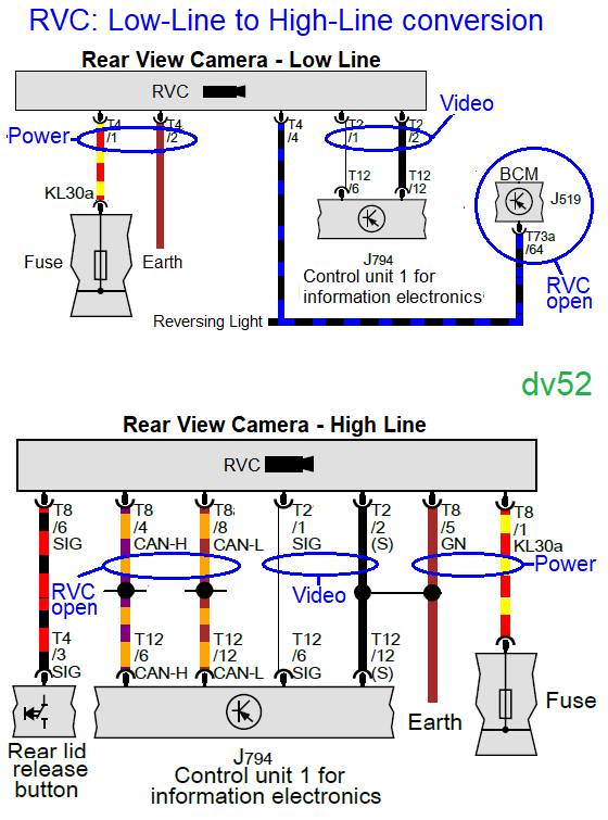
However I'm still waiting for the new cam, today I did some Investigation in advance. So my car came originally with a lowline RVC, and I mentioned like Kushdaiin, that pin 2 from the camera is there, but not comming through the car harness,. See the picture.

1000038037.jpg


So I took a multimeter and shortened pin 2 to ground, and it appears it has ground.

Also, I took apart the whole housing, since I'm only replacing the cam and keep the original latch and mechanism, to see if it would be complicated, which is not by the way. Based on what I've seen it can't get ground through any screws, since it is all plastic. So that leaves only one option, that it gets ground through the video signal wire. I was not 100% sure about this, because I already put the housing back together before I did the test with the ground. So I disconnected the video signal wire, and yes no more ground, my thoughts where right. But that doesn't explain the short to ground error that Kushdaiin experienced.

Further more, the highline cam will come with an 8 pin connector and there must come a wire from pin 3 from a 4 pin connector to pin 6 from the 8 pin connector, is this that 4 pin connector as seen on the picture below?

1000038042.jpg


So basically, if so, I need to take out pin 3 from this connector, and make a new wire from this pin 3 position to the 8 pin connector from highline cam?

Great thanks for your answer in advance.

Greets Chris.
 
Last edited:

DV52

Drag Racing Champion
Location
Australia
So that leaves only one option, that it gets ground through the video signal wire

Hmm.........this is very odd indeed!!

Yes in theory it's electrically OK for the screen wire to supply earth potential to other parts of the device - but normally it works the other way around (i.e. the screen wire TAKES earth from a separate solid wire that is the device earth).

The effective cross-section size of the screen on coax cables are designed for the low power signals on the active wire. The overall power needs of the RVC is not high - but it is nevertheless much greater than the video signal power!

Again, strange!
Don
 

Meesters

New member
Location
Belgium
Car(s)
Golf 7.5 Variant
@DV52

It is odd, I will do the test and wire it to ground when my new cam has arrived. To see if there is an error.

I have also a question, maybe you'd know.

Further more, the highline cam will come with an 8 pin connector and there must come a wire from pin 3 from a 4 pin connector to pin 6 from the 8 pin connector, is this that 4 pin connector as seen on the picture below?

1000038042.jpg


So basically, if so, I need to take out pin 3 from this connector, and make a new wire from this pin 3 position to the 8 pin connector from highline cam?

Could you confirm if this is the 4 pin connector where from pin 3 must be repinned to pin 6 the 8 pin connector from highline cam? Like Kushdaiin said before?

Pin 3 from the latch assembly goes directly to pin 6 (on the eight pin connector) on the camera now.

So basically, make a new wire between those connectors.

Thanks already.

Greetings from the other side of the world.
 
Top